.: technical related info
AVR:
If you plan on building a Bliss-Box your self, start be getting over to Ralph's site and start learning. My project was based on his design. NOTE: His projects uses 8k bytes in program space and I had to bump that up a bit. I use an ATMEGA 168 chip, its 32k bytes. I maxed the chip out, so for version 2.0 I will need to use the 128k version. Ralph has chosen to develop in linux. Although I love linux; I chose AVR-Studio on a windows platform. Also note that the 168 requires a few code changes and 1/2 watt diods, the 1 watts wont work.
DIY:
For those that want to do this their selves from ground up, there is an option for that. For you to make this adaptor you do need to have the board and chip ready. As mentioned above I'm not interested in showing the brake down on this page. So if you want to do this from scratch start by learning on Ralph's site, my source code is available on my front page including the schematic.
For the DIY version of this project you must buy the bare board which included all components on the board as shown below. The cost is $50 wired up for you or you can buy a $35 version and solder the wires on yourself. Yes it's time consuming. The $50 includes the chip, board( with components), and the wires soldered on to them (matching the colors seen below). So all you need to do is connect wires :)
The following picture shows the connections on the board.
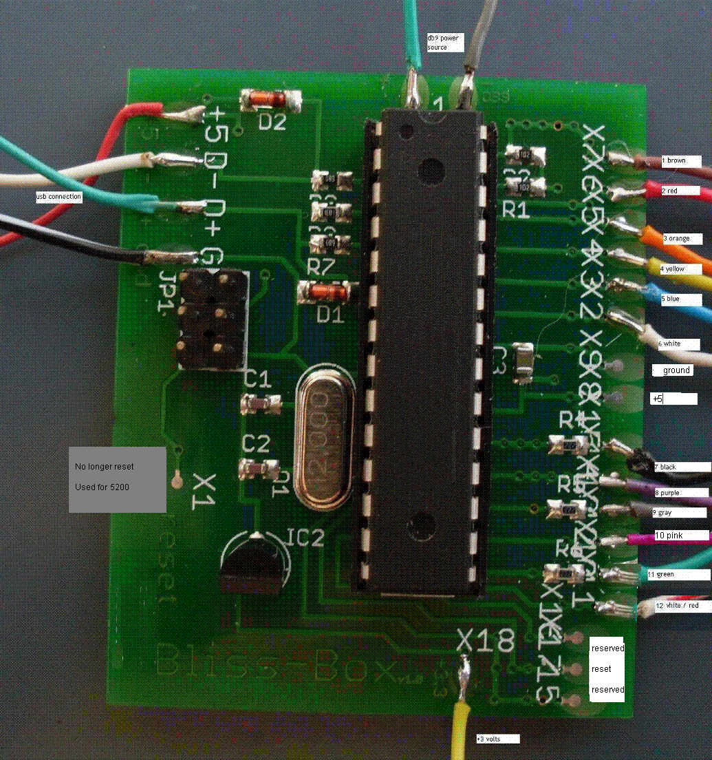 |
On the left is the USB connection. For the most part you just match the colors. Some USB cables don't follow this color code, so make sure it's right.
On top left is the power connection. The 3 volt ( on the bottom ) is only used for n64/gc. Some sources say psx needs 3 volts. This board was design for a 5 volt psx, so don't use 3 volts far anything but n64/game cube controllers. At the vary top is the power source for the db9 conenctor. It is 5 volts but its controlled via the MCU so you must use this source for db9 only.
On the right are the solder point connections. It is important to realize these colors don't match any controller, as they are all different. Below are the guides ( i.e: 1 to 4 ) means controller pin 1 to solder point 4 ( or wire 4 )
NOTE: if you need to see the labes open the image up in a new window. But the colors should look right on your monitor if its calabrated. The cables are numbered from 1 to 12 |
All connection ports are viewed looking at the console, if the pin is not mentioned it's not connected
Power diagram Key:
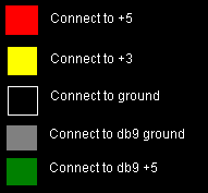
Gray'd circles are unused pins. White circles with no fill are connect to black(pin 7) othwewise connect the wire to the mathcing fillin in color ( or use the numbered lables ).

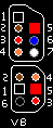
DB9 ( serial port ) |
1 to +5
2 to 4
3 to 3
4 to 2
5 to 1
6 to 7
| 7 to ground
8 to 6
9 to 5
NOTE: use db9 power source
| 
N64 |
1 +3
2 to 1
3 ground
|

Game Cube |
1 +5
2 to 1
3 ground
4 ground
-
6 +3
|
NES and visual boy |
1 to ground
2 to 1
3 to 2
4 to 3
5 to +5
6 to 5 ( arkanoid )
7 to 6 ( arkanoid )
|
mini din
full din

Turbo Grafx ( PCE )
|
1 to +5
2 to 1
3 to 2
4 to 3
5 to 4
6 to 5
7 to 6
8 to ground
|
Play station |
-
-
3 to 7
4 to 11
5 to +5
6 to ground
7 to rumble n/a
8 to 9
9 to 8
|

Atari Jaguar |
1 to 1
2 to 2
3 to 3
4 to 4
-
6 to 5
7 to +5
|
-
9 to ground
10 to 6
11 to 7
12 to 8
13 to 9
14 to 12
-
|

Super NES |
1 to +5
2 to 1
3 to 2
4 to 3
-
-
7 to ground |

Saturn |
1 to ground
2 to 3
3 to 4
-
5 to 6
6 to 5
7 to 1
8 to 2
9 to +5 |

PC-FX |
1 to +5
2 to 3
3 to 4
4 to 2
5 to ground
6 to 1
7 to ground
|
Neeo-geo / atari 5200 ( dh15 ) |
1 to +5
2 to 2
3 to 4
4 to 6
5 to 8
6 to 10
7 to 11
8 to ground
NOTE: use db9 power source |
9 to 1
10 to 3
11 to 5
12 to 7
13 to 9
14 to x1
15 to 12
x1: This is needed for the atari 5200. x1 is on the left of the board |

Dream Cast
|
1 to 1
2 -
3 ground
4 +5
5 to 2 |
NOTE about converting the neogeo port to atari 5200: If you have a reset button that connects ground to x1 (reset) you need to remove the wire going to reset and connect it to usb (-) the wire wire. In so that the x1 is now free to use with the dh15 port and so that the (-) ( white wire ) of the USB goes to that reset switch.Shorting the White USB wire to ground will reset the device as well. This is only if you intened to support the 5200.
How to cable an intellivision 1 controller
First off please note intellivision controllers are very docile, and easy to brake. Most of them don’t even work. They were not meant to last 30 years I can assure you of that. Intellivision version 1 controllers are far better built then version 2. Version 2 are already cabled and will work. Version 1 needs to be cabled like so.
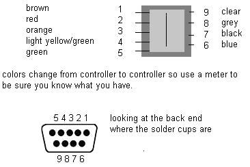
As you can see, its pretty much a dirrect match. You will see a brown tab over the controller pins. This is used to press down the plastic contact sheet over the pins. I have seen, once opened that the contacts can be problimetic and not work well any more. A simple fix is to add another tab on the one in there. I used a soft tab 16th of an inch think and made a bad controller work. Bending the pins up is not always a good idea, if you break them I don’t think it will be easy to find a replacement.
note: beyond this write up I offer no help fixing intellivision controllers
How to use a vectrex controller
In order to use a Vectrex controller you must build a patch cable or adapter. Below is a diagram to illustrate how.
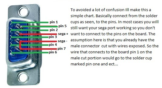
The male is where the Vectrex cable plugs in to, the female goes to the Bliss-Box. The short is a must, it tells the Bliss-Box that it is a Vectrex controller. A short is made simply by connecting the two pins. You can do this in your adapter or patch cable. Pins 7 and 5 are swapped. This patch cable/adapter is needed do to limitations on the atmega chip. If you require more info feel free to ask. Again (as the image states) , the female jack is view from the back, where the male is viewed from the front). Otherwise the image would be hard to read.
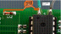
Paddles.
The paddle code has completely been redone. It now makes use of the avr and has no need for a silly timer. A capasitor is needed for player 1. Simply connect a 300pf capasitor from ground to atari power ( the green wire at the top of the board ). FYI: for the newbie types 301 means 300pf ( look it up )
|